
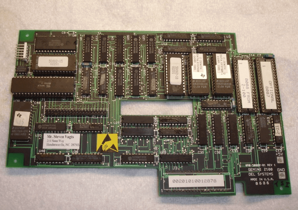
Gemini Board: Photo courtesy of Steven Vagts of Z-100 LifeLine
The Gemini Board was a PC emulator circuit board designed to plug into the Z-100 motherboard and provide better IBM-PC compatibility mainly at the BIOS level. The board had a separate 8088 processor dedicated to handling BIOS and video compatibility. You transferred your Z-100’s 8088 onto the Gemini board and also routed the video cable through the board so the Gemini could plug directly into the Z-100’s 8088 socket and video connector to provide both pass-through and IBM-PC modes of operation. You could also add an optional 8087 math coprocessor to the Gemini for even better compatibility and speed.
I first acquired an old Gemini board on eBay and bought it “at risk.” Unfortunately, it was DOA. Since most of the chips on the Gemini are soldered in place, there’s not much you can do with a bad board. That’s when Steven from Z-100 Lifeline stepped up and offered to replace my Gemini board with a fully tested and functional unit – thank you Steve!. Installing the Gemini board and figuring out its internals took some time and there are a few gotchas to watch out for which I’ll talk about in my next article on using the board.
Now on to the installation.
Installation
To install the Gemini board, you’re going to disassemble the Z-100 down to the motherboard level. You will remove everything except the motherboard and the S-100 chassis. This sounds more formidable than it really is. After you’ve done this a few times, it takes about five minutes to expose the motherboard. There are different models of the Gemini so some boards may look slightly different from the photo above. The installation and commands are exactly the same although IBM-PC compatibility may be different depending on the board. For reference, my board’s monitor ROM is MTR-150 which is one of the latest versions of the ROM released for the Gemini.
Note: Make sure you disconnect the AC plug before continuing further.
Disassembly
If you already know what you’re doing, you can skip straight to the Gemini installation steps in the Gemini Manual.
Otherwise, follow your handy Z-100 Technical Manual for disassembly instructions to thepoint where you have removed the video board which normally sits on top of the motherboard. See the photos below to see how I disassembled my Z-100.
1. Start by removing the case cover.
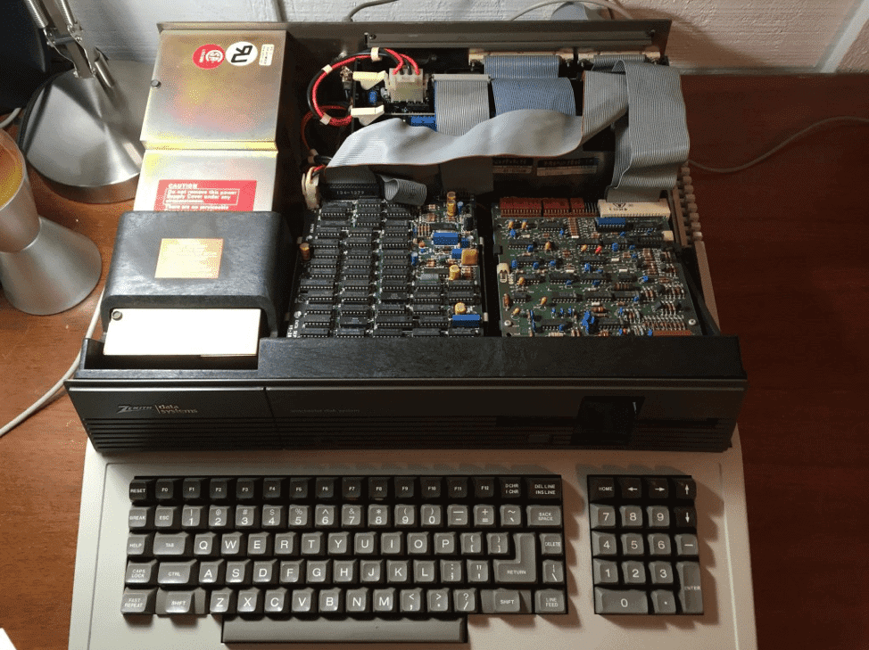
Z-100 with Case Off
2. Next unplug the cables and power connectors attached to the drive bay. I have a Winchester hard drive on the left and a 5 1/4″ floppy on the right so you may have have a slightly different configuration. I photographed and marked the tops of all cables the first time around to make sure I knew how to reattach. Unscrew the four screws holding the drive bay to the case and remove the drive bay from the Z-100. Set aside.
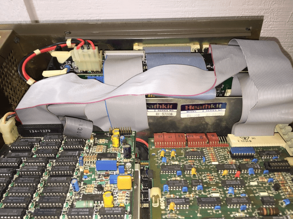
Close-up of Z-100 Drive Tray and Cables
3. Unscrew the four screws of the chassis case and remove it. It lifts right off. You will need to unplug any cables in the rear of the unit like monitor and external disk drives before you can remove the chassis case.
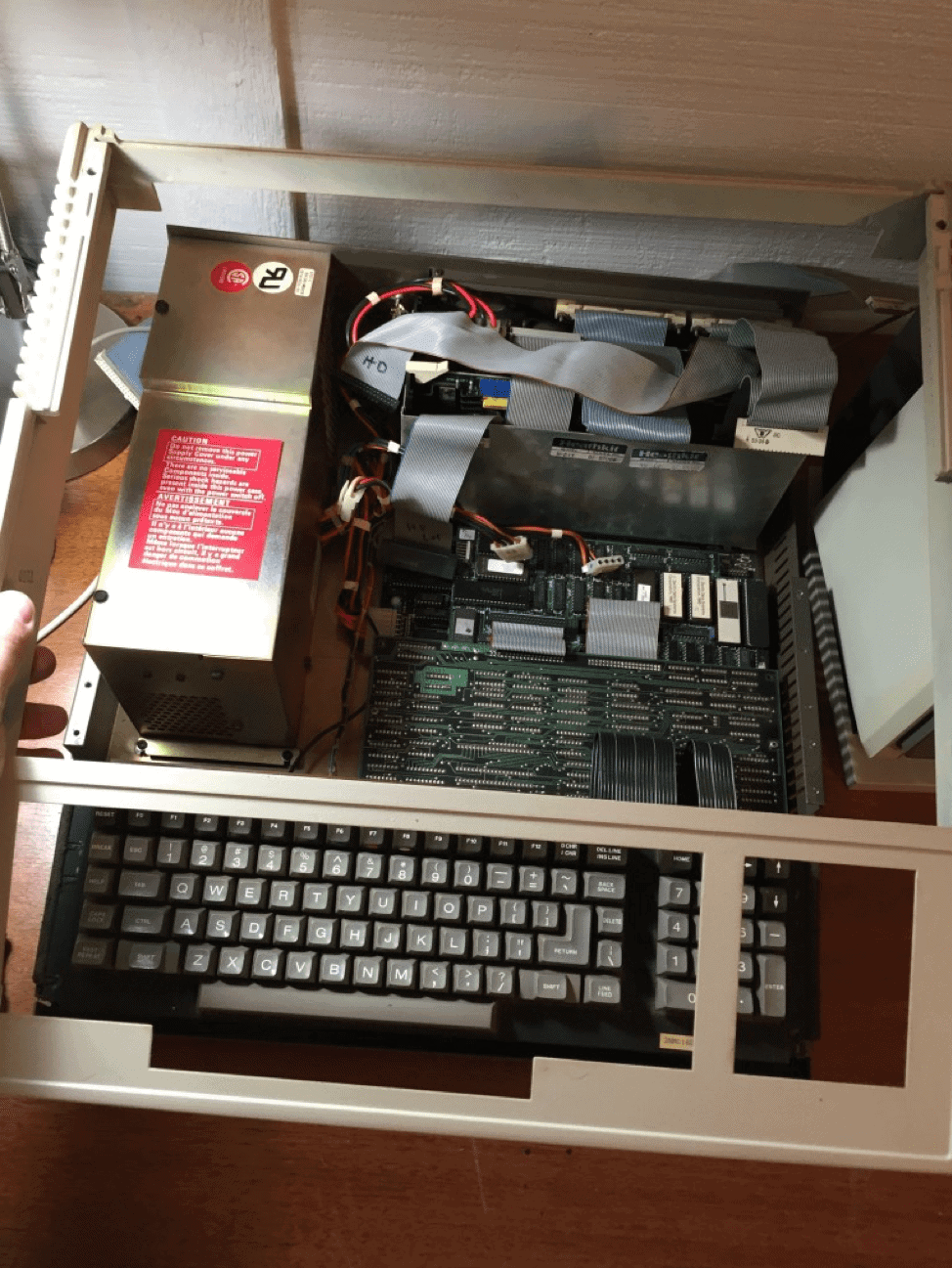
Z-100 Keyboard Removal
4. The keyboard will now lift out and you will see the upside down video board attached to the motherboard.
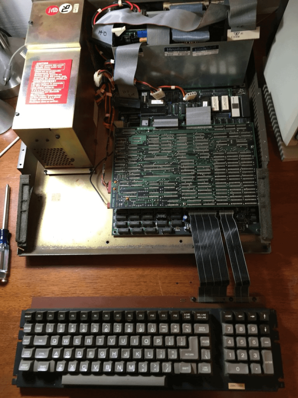
Z-100 Motherboard and Keyboard
5. You need to remove the three screws holding down the video board. When lifting up the video board, make sure to keep track of the three ceramic spacers (those white things you see in the picture). They go back on the metal stand-offs when you replace the video board.
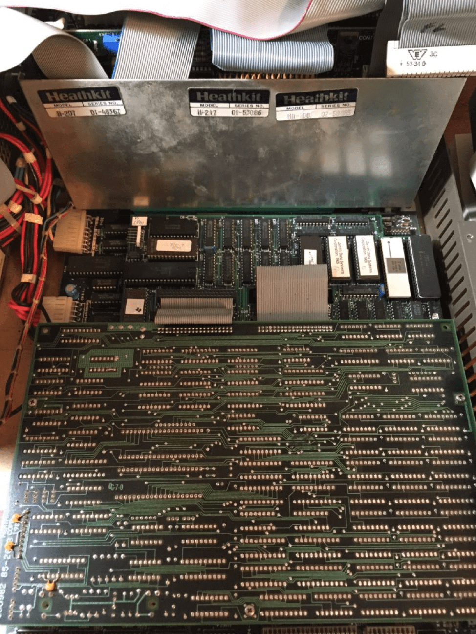
At this point, you will want to consult the Gemini manual which shows you which cables to unplug and thread through the Gemini board and also how to remove the Z-100’s 8088 chip and socket it on the Gemini board. The white chip you see on the motherboard is my 8088 (8 MHz version). Your chip may look different.
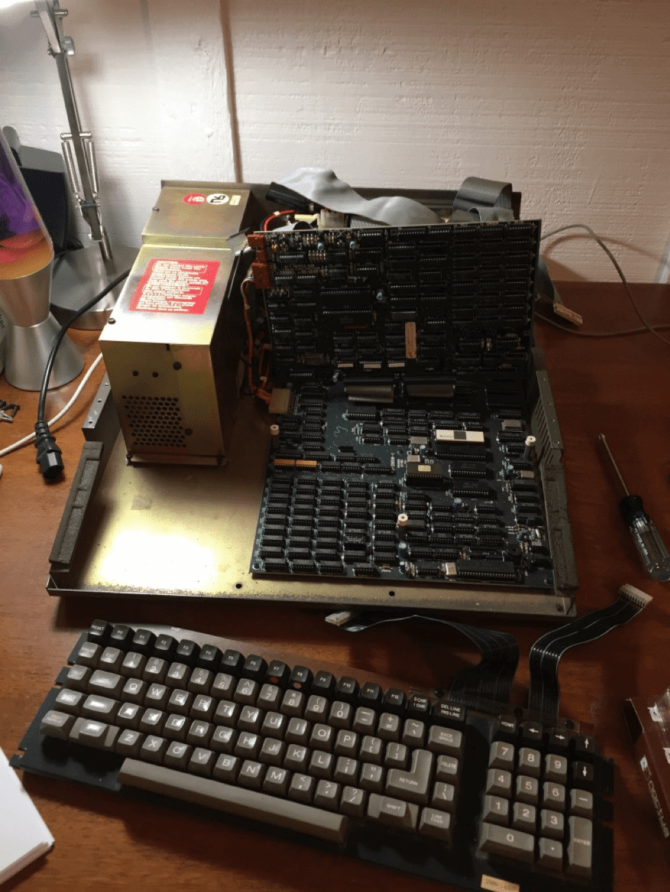
Removing the Z-100 Video Board
6. Seating the Gemini Board can be a little tricky. You have to first line up the female IDC socket with the motherboard then also align the 8088 male socket pins. The board should seat firmly onto the Z-100 motherboard like you see here. In this picture, the video board is still tilted up but cables have been threaded and attached per the Gemini manual guidelines. You can also see that I’ve socketed my Z-100 8088 on the Gemini board in the upper right-hand corner. I also have an optional 8087-2 math coprocessor socketed on the board as well right next to the 8088.
7. Now you need to put it all back together. First replace the video board like you see below and then reassemble everything in reverse order.
8. You might as well power this puppy up and see what happens now. Hopefully, you are greeted with the following screen:
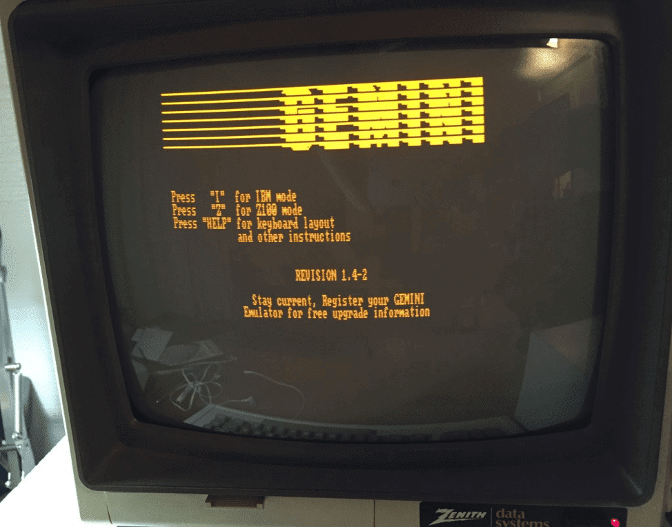
Gemini Boot Screen
If you’ve made it this far, congratulations! You have successfully installed your Gemini Board. For straight Z-100 mode, just press “Z” and the Z-100 will boot as normal. To boot into the IBM-compatible mode, press “I” and make sure you have Zenith MS-DOS v3.2 or v3.3 boot disks handy. I’ve also confirmed that you can boot Z-150 MS-DOS disks. You might also be able to boot pure IBM MS-DOS disks but I haven’t tested this scenario yet. The HELP menu gives some excellent tips for using the board like hard drive setup tips, keyboard and COM port mappings.